Articles - Pump Technology

| SUBJECT: |
WHAT YOU SHOULD KNOW ABOUT PUMP SYSTEMS IN LAYMEN'S TERMS
|
|
PRESENTED at CleanTech 2000 in Las Vegas on June 5, 2000 by Marc Treppler, MART General Manager and Engineering Manager
|
NOTE: The following discussion explains in detail how pump pressure and discharge losses occur. One such loss, easily observed when one knows what to look for, takes place at the nozzle discharge. At issue are "transitions", or the path of the solution from the manifold through the nozzles. The losses at this point, explained in the text, can be significant. Shown on the right are two such transitions.
|
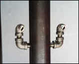 OTHERS
50% loss from Complex Transition
|
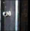 MART
MART
2% loss from Smooth Transition
|
Introduction
The purpose of this article is to help people who do not have engineering backgrounds understand the effects of pumping system performance on soil removal in a cabinet-style washing machine. While some of the information presented will be technical, we have attempted to provide it in a manner that lay people can gain a more clear understanding of washing machines to make informed decisions about their cleaning equipment and processes.
Washer makers generally publish pumping system information of some sort. Buyers rely on this information to determine the level of performance they can reasonably expect from a machine. Some manufacturers list only the horsepower of their pumps, while others provide flow and pressure data. The problem is that the data can be misleading. Quite often the data reported are not the operating specifications of their machines, but of the pump itself, under test conditions, taken by running the pump in a tank of water at 40 degrees C. with flow and pressure readings from the pump discharge. Such reporting accurately states the performance of the pump, but not of the washing machine where suction and discharge losses can significantly reduce pump performance. The only data of value is the flow and pressure that discharges from the nozzles because this represents the actual energy available for parts cleaning after all losses are deducted.
Pumping system performance is expressed as efficiency, which is a measure of electrical power, converted into fluid power. At a theoretical efficiency of 100%, a pumping system would have no losses because all of its electrical power would be turned into fluid power. The equation to calculate efficiency is:
|
EFF = GPM x Head x Specific Gravity
Horsepower x 3960
EFF – % efficiency
GPM – Flow in Gallons per minute exiting system
Head – System discharge pressure expressed in feet of head
Specific Gravity – specific gravity of pumped solution at operating temperature
Horsepower – horsepower of pump motor
|
There are theoretical constraints in a pump that limit the maximum possible efficiency to well below 100%. A pump driven by a 20 horsepower motor, for example, cannot deliver 20 horsepower of power at the nozzles. It is not unusual for a 20 horsepower pump to deliver less than 10 horsepower of power at the nozzles. The challenge for the engineer is to design a solution delivery system that maximizes the use of power available from the pump motor. Some washing machine makers do not consider these factors in their designs or report the solution delivery system losses in their published data.
This article will examine how the solution delivery system design can affect cleaning results. It will cover pumping system design and application, and how data is acquired and published, so a buyer can know the usefulness of the information provided by a washer manufacturer.
Centrifugal Pump Curve
Each centrifugal pump has a set of operating characteristics, reported as a "curve", that indicate the pump performance at various operating pressures and flows. Certified pump curves are available from the pump manufacturer. The curves are developed through a rigorous set of testing as defined by the Hydraulic Institute. The pump curve reports the output of a pump in terms of flow and pressure for different impeller diameters, and the horsepower required to drive the pump at each of its operating points.
A centrifugal pump operating in a washing machine will have load restrictions at its suction and discharge. The load on a centrifugal pump in a wash machine is created by the solution flowing through the suction, piping, elbows and the exit through the spray orifices. The total load will determine the specific operating flow and pressure point for the pumping system which, in turn, determines the horsepower required to drive the pump.
Number of Nozzles
The size, shape, quantity and design of the orifices all affect the load on the pump. In a well-designed flow system the effects of the piping system will be minimal so that the majority of the load will come from the orifices.
Equations of Flow
The equation for flow through an orifice is given by:
Q =19.636Cp* d2 *SQRT(H)
Q = flow rate in Gallons Per Minute (GPM)
D = diameter of nozzle in inches
H = pressure at nozzle in feet of liquid
Cp = orifice flow coefficient – from table
|
The total system flow can be determined by multiplying the flow for one orifice by the total number of nozzles in the system. Thus the equation for total system flow is:
Qs = N X Q
Qs = total system flow in GPM
Q = flow for each orifice in GPM
N = Total number of nozzles in spray manifold
|
Accuracy of Flow Per Nozzle
It is important that the nozzles be uniform and identical so that an accurate prediction of flow can be computed. Small differences in the size or smoothness of the entrance to the nozzle can change the predicted flow at various pressures. Generally, nozzles must be accurately machined and then tested to determine the flow coefficient. Some examples of various flow coefficients are shown in table 1. Note that the smooth tapered entrance coefficient is closest to 100%. Machined stainless steel nozzles available from several manufacturers are the best choice for maximum velocity efficiency. When erosion changes the shape and flow rate of a nozzle, a new nozzle can restore the washing machine to its original level of performance.
System Operating Point where the two Characteristic Curves cross
An optimum system design will have no appreciable losses in the piping or manifolds so that the nozzles will determine the operating parameters of the system. Assuming no losses in the piping the operating point of the washing pump and nozzles is where the pump curve crosses the manifold nozzle flow equation. At this point the pressure and flow for both the pump and manifold are equal. An example of a pump curve and manifold curve is shown in Figure 1. Using this analysis as the basis for the design of a pump and manifold system, one can optimize the energy used from the pump motor. Since the energy available from a pump motor is fixed, the impeller must be trimmed or the number and size of the nozzles changed to use all the available motor energy (see Figure 2). The first design yields an operating point that falls below the full available horsepower of the motor. For illustration, assume this pump is operated with a 20 horsepower motor. The pump and manifold will run without overloading at the first design point so that only a portion of the available motor energy is used. Since the motor is under-loaded it will run inefficiently because most motors are designed to run at maximum efficiency only at full load. Likewise, a washer maker could state that it is providing a 20 horsepower motor but the pumping system pressure or the flow is reduced so that the machine only delivers 10 horsepower or less of energy at the nozzles. To make this system more effective would require a larger diameter impeller or a greater flow through the manifold. A larger diameter impeller would increase system pressure and flow to design point A. More nozzles or larger nozzle orifices would decrease system pressure and increase system flow to design point B. Either of these system changes would optimize the use of the pump motor by fully loading the motor to its design rating of 20 horsepower.
Some washer makers do not engineer their pump suctions and discharges but, rather, simply install pumps without attempting to optimize performance. The manufacturers that do engineer their systems, in order to simplify the design process, might not take into account the many variables that affect pump performance. In the above analysis, factors such as piping losses, fluid viscosity and temperature variations are assumed to be minimal. As stated earlier, many washer manufacturers publish the pressure and flow, but these data are taken from the pump curves supplied by the manufacturer. A test of the pumping system in the washing machine takes its measurement data at the nozzles so that all the variables are considered yielding the true pressure and flow. With this data the manufacturer can "fine" tune the design, adjust the pump impeller size, and alter the manifold nozzles to fully optimize the use of the energy available from the pump motor.
Impact Pressure Vs Pressure
There are two factors relating to pressure that affect cleaning: Impact pressure and static pressure. Static pressure involves "system" pressure and the pressure at the exit of the nozzles. This is the force per unit area that the fluid exerts on the pump, discharge piping, manifold, and nozzle walls as it moves through the system. Once this fluid leaves the nozzles its static pressure instantly drops to zero. Because there are no walls to constrain the fluid at discharge, the fluid pressure and atmospheric pressure must be the same. All the static pressure energy of the fluid is converted to dynamic energy of velocity. The mass of fluid moving at a given velocity is what "impacts" the parts to be cleaned, thus creating the cleaning force. This impact force can be calculated from the equation:
F=2A(P)
F = force in pounds
A = orifice area in square inches
P = exit pressure in PSI
|
Impact force is the conversion of momentum energy into static force from the cleaning solution slamming into the parts to be cleaned. Impact pressure is the impact force spread out over the area of impact and expressed as force per unit area. The impact pressure varies depending on the nozzle spray pattern and the energy available at the nozzle. Different types of nozzles have different spray patterns. The type normally used in washing is a flat fan type. These nozzles generally create a flat spray pattern with a spray angle of from15 to 100 degrees (see figure 3). The shape of this pattern can be tapered at the edges so that, by overlapping the spray from adjacent nozzles, the solution is evenly distributed throughout the wash load. It is crucial to have even distribution from the nozzles for soil removal. Uneven distribution causes stripping and missed cleaning areas on the surfaces being cleaned. The impact force created from a flat fan nozzle is the total impact force divided by the area of spray coverage. Nozzle manufacturers have created empirical formulas for impact pressure for various nozzle spray angles. The equation for impact force and pressure, for a nozzle with a solid stream (zero degree spray angle), is the same as for a fan nozzle. The solid stream produces an impact pressure several orders of magnitude higher because all the force is concentrated into a very small area. Table 2 has a tabulation of the expected impact pressures for various spray angles and pressures.
CALCULATED IMPACT PRESSURE in PSI @ 12 Inches from Nozzle Tips
SYSTEM
| Nozzle Flow |
|
Nozzle Angle
|
| PSI |
GPM |
|
0 |
5 |
15 |
25 |
40 |
50 |
65
|
| 80 |
10.0 |
|
152.0 |
4.3 |
1.4 |
0.8 |
0.6 |
0.5 |
0.3
|
| 100 |
10.0 |
|
190.0 |
4.8 |
1.6 |
0.9 |
0.6 |
0.5 |
0.4
|
| 120 |
10.0 |
|
228.0 |
5.3 |
1.7 |
1.0 |
0.7 |
0.6 |
0.4
|
| 140 |
10.0 |
|
266.0 |
5.7 |
1.9 |
1.1 |
0.7 |
0.6 |
0.4
|
| 160 |
10.0 |
|
304.0 |
6.1 |
2.0 |
1.2 |
0.8 |
0.7 |
0.5
|
| 180 |
10.0 |
|
342.0 |
6.5 |
2.1 |
1.3 |
0.8 |
0.7 |
0.5
|
| 200 |
10.0 |
|
380.0 |
6.8 |
2.2 |
1.3 |
0.9 |
0.7 |
0.5
|
|
|
|
|
|
|
|
|
|
|
| 100 |
6.0 |
|
190.0 |
2.9 |
0.9 |
0.6 |
0.4 |
0.3 |
0.2
|
| 100 |
9.0 |
|
190.0 |
4.4 |
1.4 |
0.9 |
0.6 |
0.5 |
0.3
|
| 100 |
12.0 |
|
190.0 |
5.8 |
1.9 |
1.1 |
0.8 |
0.6 |
0.4 |
| 100 |
15.0 |
|
190.0 |
7.3 |
2.4
|
1.4 |
0.9 |
0.8 |
0.6
|
| 100 |
18.0 |
|
190.0 |
8.7 |
2.8 |
1.7 |
1.1 |
0.9 |
0.7
|
| 100 |
21.0 |
|
190.0 |
10.2 |
3.3 |
2.0 |
1.3 |
1.1 |
0.8
|
| 100 |
24.0 |
|
190.0 |
11.6 |
3.8 |
2.3 |
1.5 |
1.3 |
0.9
|
| 100 |
27.0 1 |
|
190.0 |
13.1 |
4.3 |
2.6 |
1.7 |
1.4 |
1.0
|
|
|
|
|
|
|
|
|
|
|
| 110 |
13.5 |
|
209.0 |
6.9 |
2.2 |
1.3 |
0.9 |
0.7 |
0.5
|
| 140 |
15.0 |
|
266.0 |
8.6 |
2.8 |
1.7 |
1.1 |
0.9 |
0.7
|
| 160 |
16.0 |
|
304.0 |
9.8 |
3.2 |
1.9 |
1.3 |
1.1 |
0.7
|
| 200 |
18.0 |
|
380.0 |
12.3 |
4.0 |
2.4 |
1.6 |
1.3 |
0.9
|
| 250 |
20.0 |
|
475.0 |
15.3 |
5.0 |
3.0 |
2.0 |
1.7 |
1.2
|
| 300 |
22.0 |
|
570.0 |
18.4 |
6.0 |
3.6 |
2.4 |
2.0 |
1.4
|
Table 2 Impact Pressure for various Nozzle Angles Vs Pressure & Flow
Note that in Table 2 the first set of data is for constant flow out of the nozzle. It can be seen that the impact is proportional to pressure change. Higher pressures deliver higher impacts for a given nozzle spray angle. The second set of data shows impact pressures for a constant pressure with increasing flows. Here the impact pressure for a zero degree nozzle is constant regardless of flow from the nozzle. The nozzles with spray angles greater than zero have impact pressures proportional to flow, and a higher flow has higher impact pressure. The reason is that the area of coverage is the same for a given nozzle spray angle but, since the volume or mass flow rate increases, the impact pressure increases as well. It is also important to note that the impact pressure doubles for a given spray angle with a doubling of flow, whereas a doubling of pressure only increases impact pressure by 1.414 times (square root of 2). The last set of data indicates a set of pressures and flows that could be expected from a washing machine with progressively larger pumps and motors. Again, impact pressure is proportional to both flow and pressure except for the zero degree nozzles. A zero degree nozzle produces an impact pressure far in excess of the nozzles with spray angles. (Note: 15- and 25-degree nozzles are the angles that most nozzle manufacturers offer as standard products). Impact for nozzles with greater than zero degree spray angles is reduced with distance because the area of coverage expands by the distanced squared. Each doubling of distance reduces impact by a factor of 4. The impact force of a zero degree nozzle, in a cabinet-style washer, does not reduce with distance. The impact area is constant so the impact pressure remains constant as long the spray pattern remains intact. A zero degree nozzle operating in a typical washer could have a controlled pattern for 20 or more feet and still maintain its high impact pressure.
Impact pressure is one of the major forces that effect cleaning. With any soil, the bond between the part to be cleaned and the soil must be broken. Impact pressure is one method of breaking the bond. Impact pressure releases soils from the substrate and flow washes them away. Flow is not a substitute for impact pressure. The impact pressure must be sufficient to break the bond. Higher flow speeds up the time it takes to cover the surface because it produces a wider stream. Unfortunately there are no formulas available to determine the minimum impact pressure required to break a soil bond. The only reliable method is to test the proposed impact pressure under actual washing conditions. Washer manufacturers with greater experience have a "feel" for the impact pressures required. While chemical and heat play a critical role in removing some types of soil, carbon, paint and scale do not react well to chemical so the most certain method for removal is to blast off the soils with high impact pressure. Before making a final decision it is best to get a demonstration under actual conditions from the washer manufacturer.
Efficient Design of Piping System
Earlier in the discussion of washing pressures and flows we chose to ignore losses associated with the piping system, assuming that they were minimal. While this does apply to a well-designed system, in a system that is poorly designed the discharge losses can consume a significant portion of the available pump horsepower. Losses in piping are well understood, and there are standard design references for designing a piping system in which losses will be minimal. Flow rate is the main criterion to determine the losses through a specific size of pipe. Smaller pipe sizes with the same flow rate have increased friction and higher pressure losses. Losses are normally presented as a loss of pressure head per 100 feet of pipe. The smoothness of the pipe, the pipe material, the flow velocity and viscosity of the solution flow through the pipe effect losses. For a viscosity close to water the velocity should be kept to less than 15-20 feet/second in the piping to keep the losses low. Too small a pipe diameter from the pump to the manifold can represent a significant loss of pressure at the spray nozzles. For example, lets assume a 100 PSI system with a flow of 200GPM. If the system has 20 feet of 1.5-inch diameter discharge pipe the loss in pressure would be over 19 PSI, while the loss with a 2-inch pipe would only be about 6 PSI. The loss with the 1.5-inch pipe represents 19% of the system pressure while the loss with the larger pipe is only 6%. Note how significantly losses are reduced by one step up in pipe size. Elbows represent another potential for losses. As a general rule of thumb each elbow equals 5 to 10 feet of pipe. A washing machine with 20 feet of pipe and 5 elbows will have pressure losses equal to 45 to 70 feet of straight pipe. It is clear that elbows should be avoided whenever possible because they can create potential losses that are greater than the total length of pipe.
The actual losses through elbows can be predicted more accurately by an equation that uses a friction coefficient and the velocity of flow through the elbow to calculate a pressure head loss. Cameron presents a set of tables with friction coefficients for various pipe fittings. In the above example of 200 GPM in a 2 inch pipe, the velocity is 19.1 ft/sec and friction loss is 1.55 PSI for each elbow.
The manifold itself provides another potential for loss. Large passages that reduce friction will minimize such losses. A general rule is that the passage area should be 10 times larger than the total nozzle area. In no event should the total area be less than 4 times the total nozzle area.
The last loss occurs at the fluid exit through the nozzle. Refer back to Table One and note the different coefficients at the nozzle exit. The best has a coefficient of 98% (similar to a machined flat fan nozzle) while the worst (similar to a drill hole in a pipe) has only a 52%coefficeint. The net result of this difference is the nozzle can account for a 50% velocity loss in the system. The system power is being used to force the fluid through the nozzle instead of being used for cleaning.
Measurement of Pressures
After the design work and engineering are finished, a prototype system is built and its operating parameters are measured. Measurement takes all the engineering predictions out of the equation and gives us a true measurement of the predicted result.
A pressure and flow reading of the solution exiting the nozzle is not as simple as it sounds. Keep in mind that the pressure and flow of a centrifugal pump is affected by the flow path and open area of the nozzles. As such care must be taken to be sure that the measurement technique does not affect the performance of the system. A pressure gage can not simply be screw into a nozzle port as this would reduce the total nozzle open are and increase the pressure in the manifold. A separate opening must be made in the manifold and the gage connected at this point so that total nozzle open area remains constant. Generally the gage must be of a type that is accurate to within a few percent. It must be calibrated on a regular basis. It should have a large easy to read dial with increments of 1 PSI and it should be fluid damped to take slow down the small pressure fluctuations that are common in any system. Once an accurate pressure reading is made the engineer can immediately evaluate the system and find if the system is performing as expected.
Flow can be measured by several methods. One method is to use a flexible hose connected over one of the nozzles to collect all flow from that nozzle. Care must be taken that this system is carefully designed so that the flow line does not affect the nozzle output. The line should have at least 10 times the cross sectional area of the nozzle. The flow can now be measured with a flow meter connected to the flow line to measure the output directly in gallons per minute
Efficiency Use of Power
In this article we have reviewed the basic hydraulics of an industrial cabinet-style parts washer. In particular we reviewed the workings of a centrifugal pump supplying fluid to a spray manifold and how the pump motor's horsepower is utilized for cleaning work. By applying the simple formulas, measurements and data when considering a washing machine one can determine the manufacturer's knowledge and competence regarding the performance of its equipment. When viewing a machine, one can take note of the pipe sizes, lengths and elbows, and calculate the length of pipe flow; and note the number of nozzles, nozzle size and degree of fan pattern that is stamped on the nozzles. With this analysis it is possible to know with reasonable certainty (a) the expected pumping system losses and, therefore, what flow and pressure the system can deliver, and (b) the impact pressure the system should produce.
A reasonable question for a manufacturer is whether its pump data are taken at the nozzles, and the amp draw or loading of the pump motor when operating. The operating load should be at or near the full load ratings on the nameplate of the motor to use the purchased power efficiently.
Efficient transfer of energy from the pump motor to the wash load must be considered when evaluating one system against another. If the critical performance elements are not met, the washing machine will have a high operating cost relative to the cleaning results it will produce. Factors that effect the efficient transfer of energy include:
- Proper impeller sizing and nozzle sizing to optimize use of purchased horsepower.
- Properly designed nozzles and properly selected spray angles
- Minimized pipe losses by proper size selection,
- Limited Pipe length and limited number of elbows in flow path
- smooth size transitions
- Proper manifold cross section area
These design parameters change the overall effectiveness of the washing machine. Poor execution of a design can result in widely varying cleaning performance from one manufacturer to the next. Be aware that the cleaning results can vary greatly from one manufacturer to another, even when both washer makers use the same horsepower pump from the same pump manufacturer. For details of MART Pumps see Pump Systems.
References:
Sears & Zemansky Physics
Spraying Systems Design Handbook
Pump Handbook, Second Edition
Cameron Hydraulic Data
|
|
|